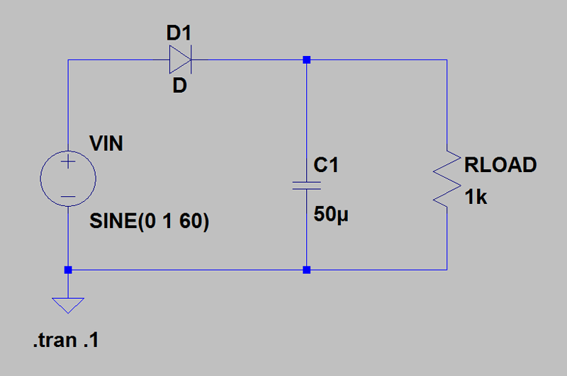
PHASE is the phase of the source, zero by default. This parameter is irrelevant for linear circuits. AMP is the amplitude of the sinusoidal source (in V or in A). To perform a frequency analysis in sinusoidal mode, you must declare a source in AC mode, with the following syntax: Vxxx N1 N2 AC (AMP) (PHASE) Here is the plot of V2 against V1: figure(figsize=(6,6)) from lectureSpicePrint import lectureSpicePrint The lectureSpicePrint.py python function described in Reading SPICE outputs with Python allows you to read this file (in some cases the exported values are complex). The resulting text file contains one column for v-sweep, one column for v (2). In this case, we can run the file with ngspice without opening the ngspice console (batch mode with the -b option):

To retrieve the data in python (or in Mathematica), we will replace the PLOT command with the PRINT command, redirecting the output to a file: RLC Circuit In the present case, the curve obtained is linear because the circuit is linear. The curve plotted is the voltage of node 2 as a function of the swept voltage (v-sweep), which here is the voltage of the source V1. To process this file with ngspice, open ngspice from a console then run source circuit-RLC-1.cir The first line is the name of the circuit. cir file for the previous circuit, with DC analysis: RLC Circuit The description of the circuit and the commands are placed in a. START1 is the start value, STOP1 the end value and INC1 the increment. SRC1 designates the source (voltage or current) whose value we want to vary. DC command actually performs a sweep of voltages or dc currents, that is to say having a constant value. You can also place all the commands (without the dots) between the two commands.
SPICE CIRCUIT PROGRAM CODE
The V symbol attached to 1 is not taken into account by SPICE: it is added to make the code more readable.Ĭontinuous scanning is defined by the. For example, a source applying a direct voltage of 1 volt will be defined by: V1 1 0 DC 1V To perform a continuous analysis, the DC option must be added to the sources. It is also necessary to specify the type of voltage source, which depends on the type of analysis that is to be carried out. The description of this circuit is not entirely complete. Here is the description of the previous circuit with numerical values for the passive components: V1 1 0

The syntax of capacitors and inductors is similar, with names starting with C and L. To enter a very small or very large value, one of the multiples defined in the following table can be used: Symbol N1 and N2 are the two nodes of the source: the voltage applied is by convention VN1-VN2.Ī resistance is defined by: Rxxx N1 N2 VALUE The name begins with V and xxx is a name that identifies the source if there is more than one. This circuit has 3 nodes (not counting the mass).Ī voltage source is defined by the following syntax: Vxxx N1 N2
SPICE CIRCUIT PROGRAM SIMULATOR
Incidentally, PSpice ® from Cadence Design Systems is the first simulator that can be run on a PC, making the transition from requiring a mainframe.Īlthough initially designed as a simulator for electronic circuits, it has now become an essential tool for board design that transmits electrical signals and requires analog elements utilizing high-speed CPU operation.It is first necessary to number the nodes of the circuit, by assigning the number 0 to the mass.

This was made possible due to advancements in production technology.

However, the switch to electronic circuit design following the advent of computers, combined with an increase in the number of elements that can be incorporated into ICs, laid the foundation for SPICE. Until SPICE, IC design was carried out entirely by hand. Device ModelĪ device model is an analytical expression that was developed based on theoretical and experimental study. More specifically, it is a general-purpose circuit simulation program that provides linear AC analysis, non-linear transient analysis, and nonlinear DC analysis.Īnalysis is performed by solving combinations of theoretical and experimental (device model) equations representing the behavior of elements based on Kirkhoff's current and voltage laws, utilizing modified nodal point analysis.


 0 kommentar(er)
